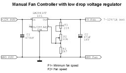
 Schematic of the LM2941 fanregulator |
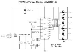 Schematic of the LM3914 Voltage Monitor |
Download Schematic in Circuitmaker2000 format |
Download Schematic in Circuitmaker2000 format |
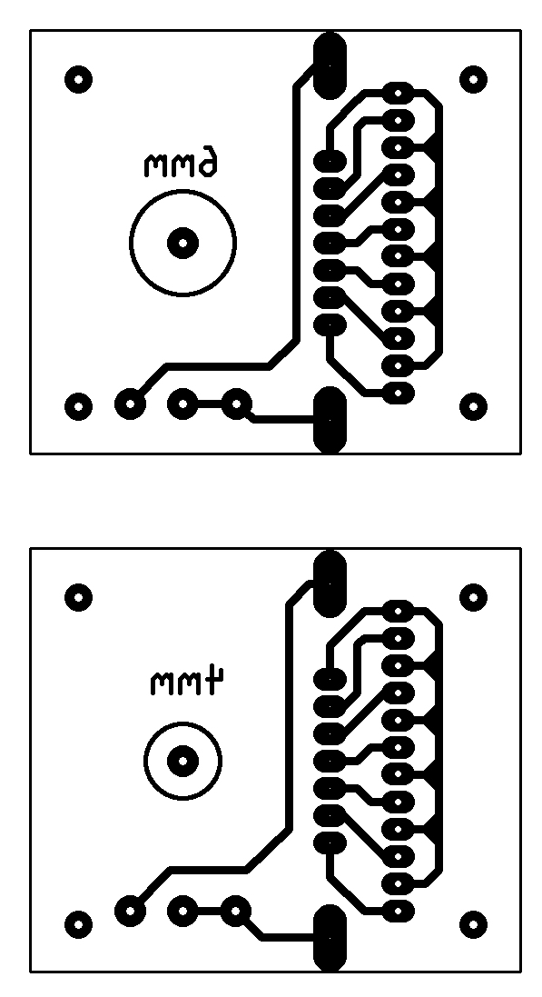 Display PCB layout |
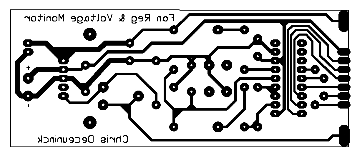 Fanregulator & Voltage Monitor PCB layout |
Download PCB layout in Circad'98 format |
Download PCB layout in Circad'98 format |
I made two different versions of the display PCB layout because I didn't know if I could obtain a potentiometer with a 4mm shaft, so a layout for a 6mm shaft potentiometer is also provided.
The part list and component layout will follow as soon as I can find some time to do it...
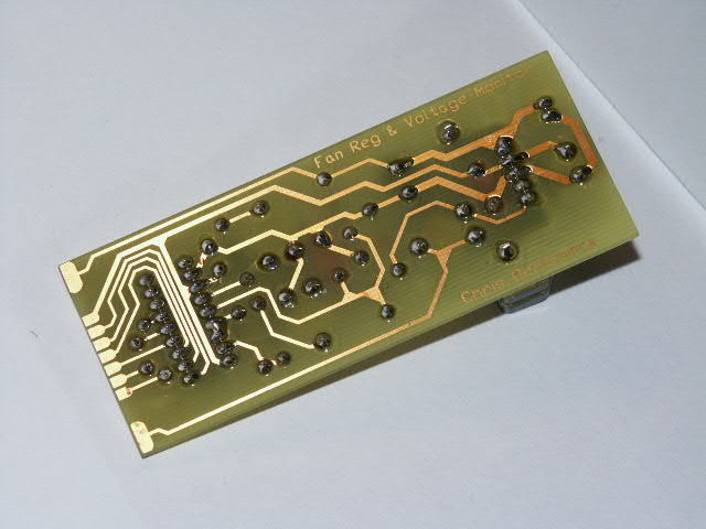 Solder side of the Fanregulator & Voltage Monitor |
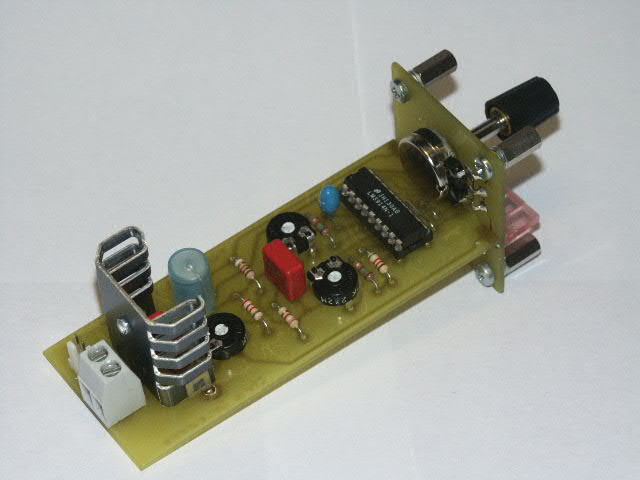
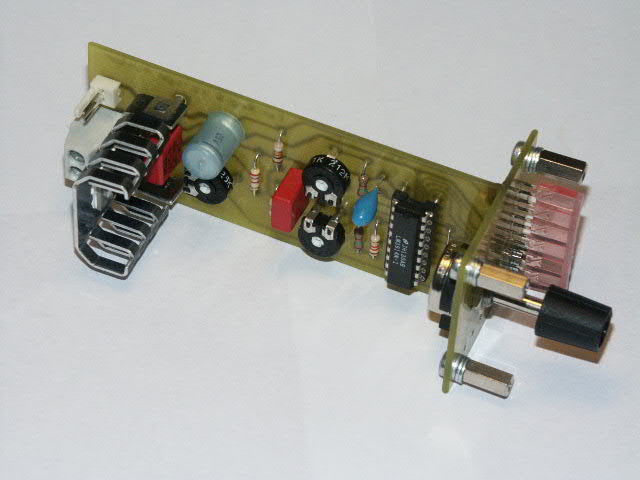
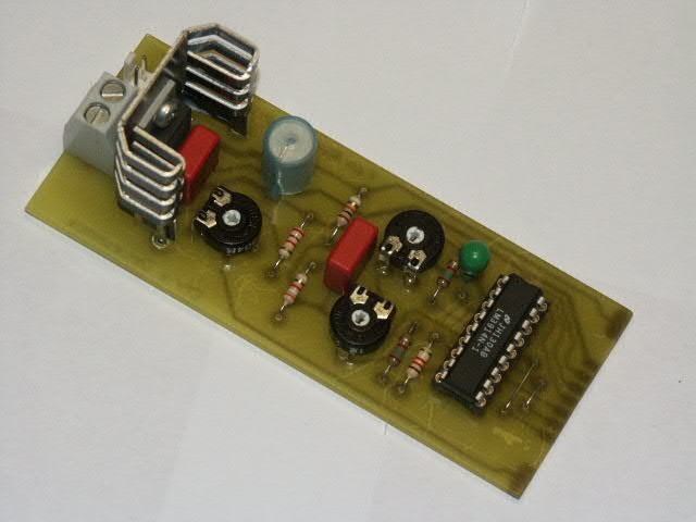 Component side of the Fanregulator & Voltage Monitor |
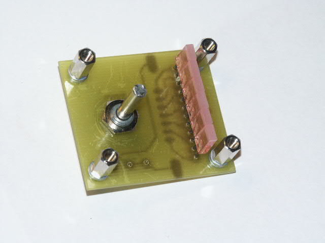
 Solder side of the Monitor Display |
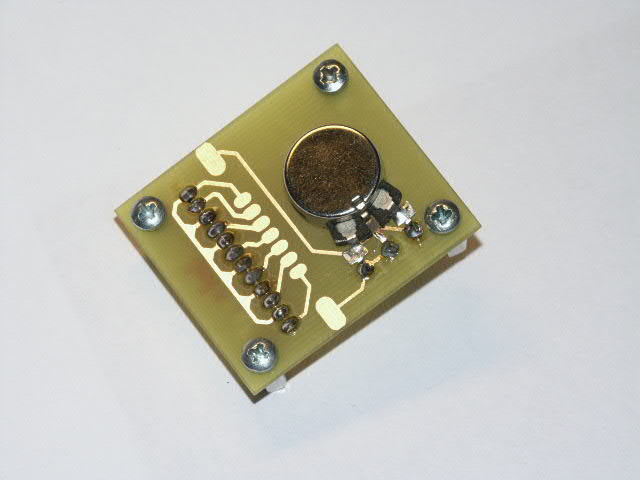
 Component side of the Monitor Display |
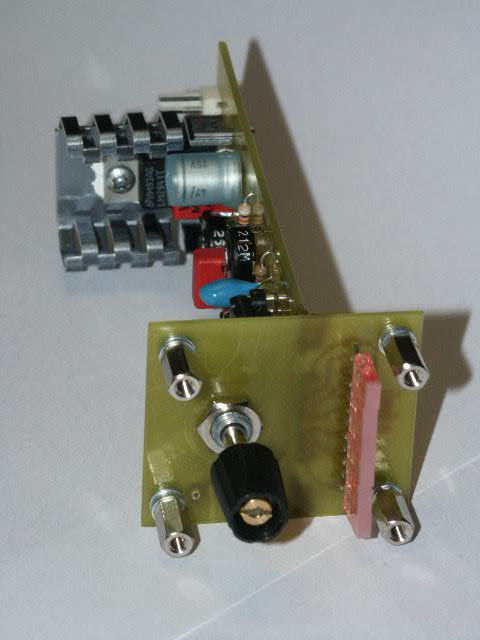
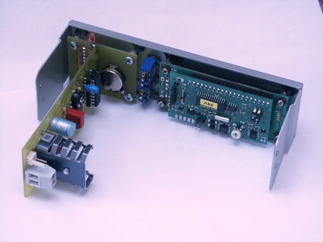
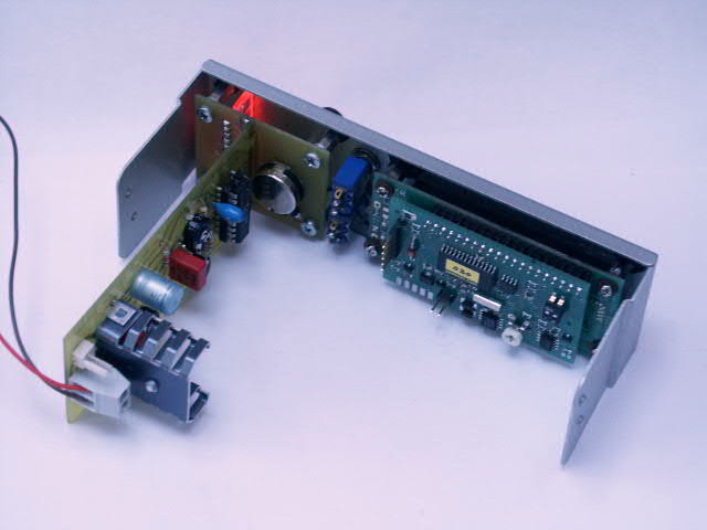
 Mounted PCB's |
 Idem in the right position for the bezel |
The two PCB's are soldered together by means of the solder pads at the edge of the main PCB, and the pads in the middle of the display PCB.
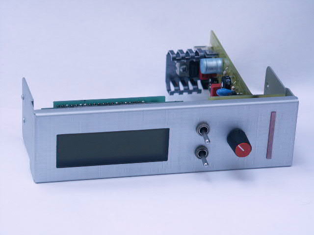
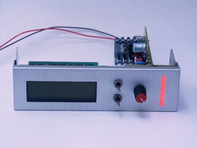
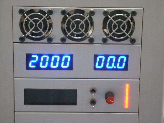
 Front view |
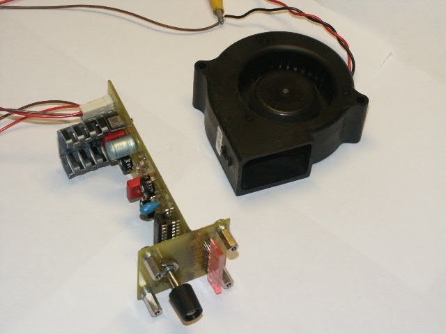 Test with a Nidec Gamma28 blower |
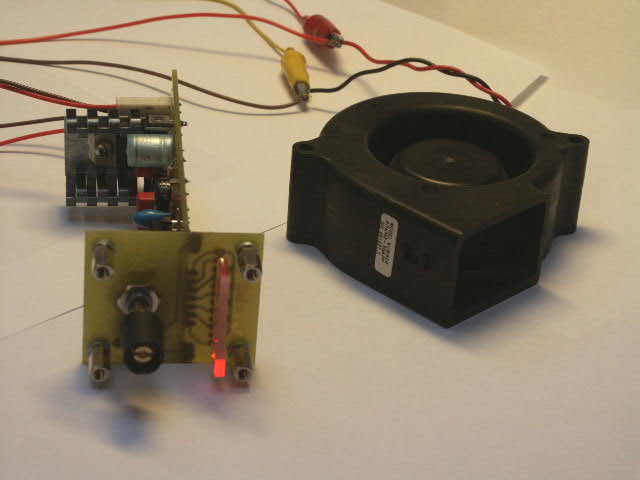 Minimum speed (7V) |
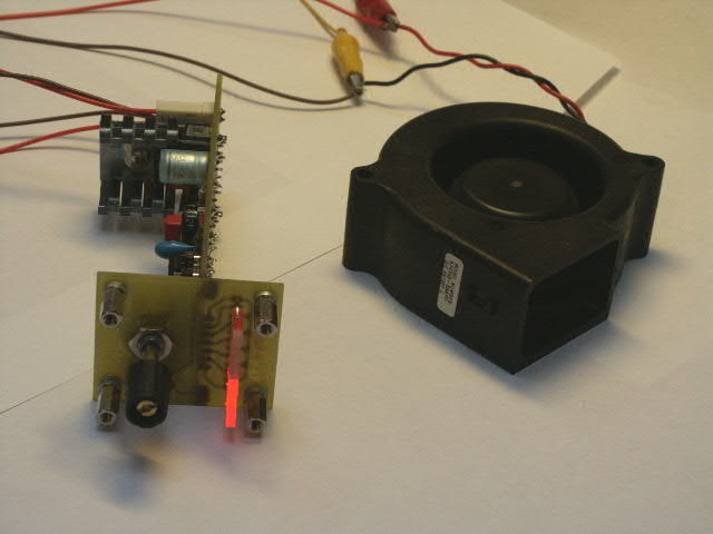 Intermediate speed (9V) |
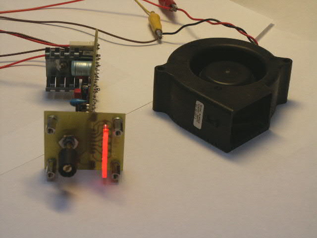 Full speed (12V) |
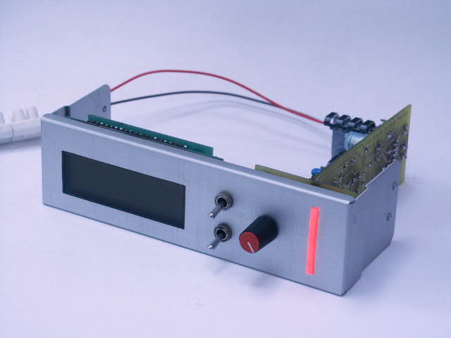
In the next pictures the fan reglator & voltage monitor is mounted into a Lian Li bezel, together with my Seetron LCD (not powered on)
 Mounted... |
 Rear view |
 Other view |
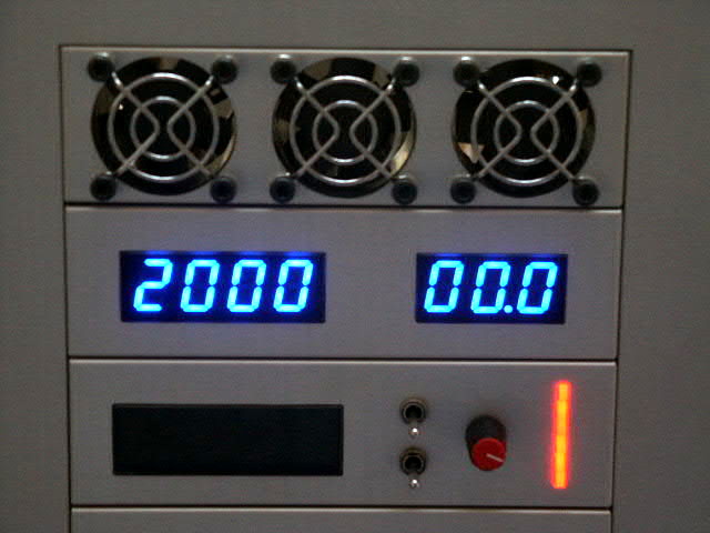
 In action... |
 Rear view |
 Other view |
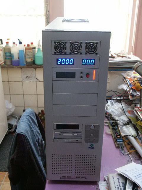
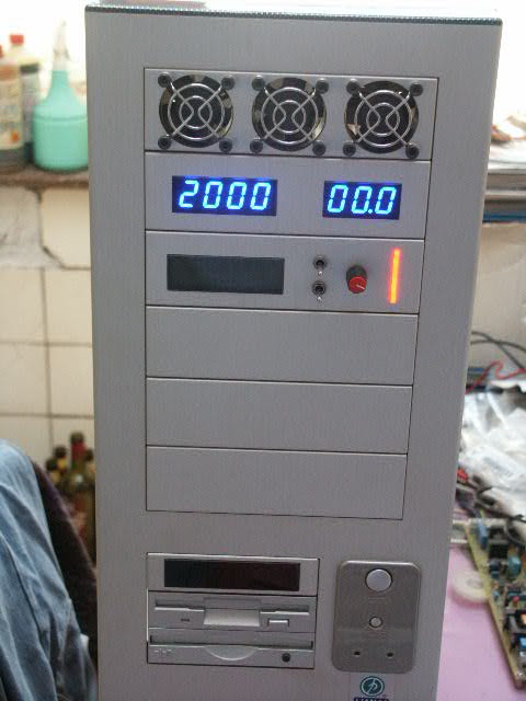
Mounted in the front panel of my PC-70...
 |
 |
General views of the front panel...
 |
 |